Flow Meter Transmitters
4–20 mA transmitter options for liquids and gases — including HART and Modbus variants. Options W2, W2-1, W3, and W3-1 are CSA/NRTL and ATEX approved for hazardous locations. All transmitters require a 24 Vdc power supply (PS-24).
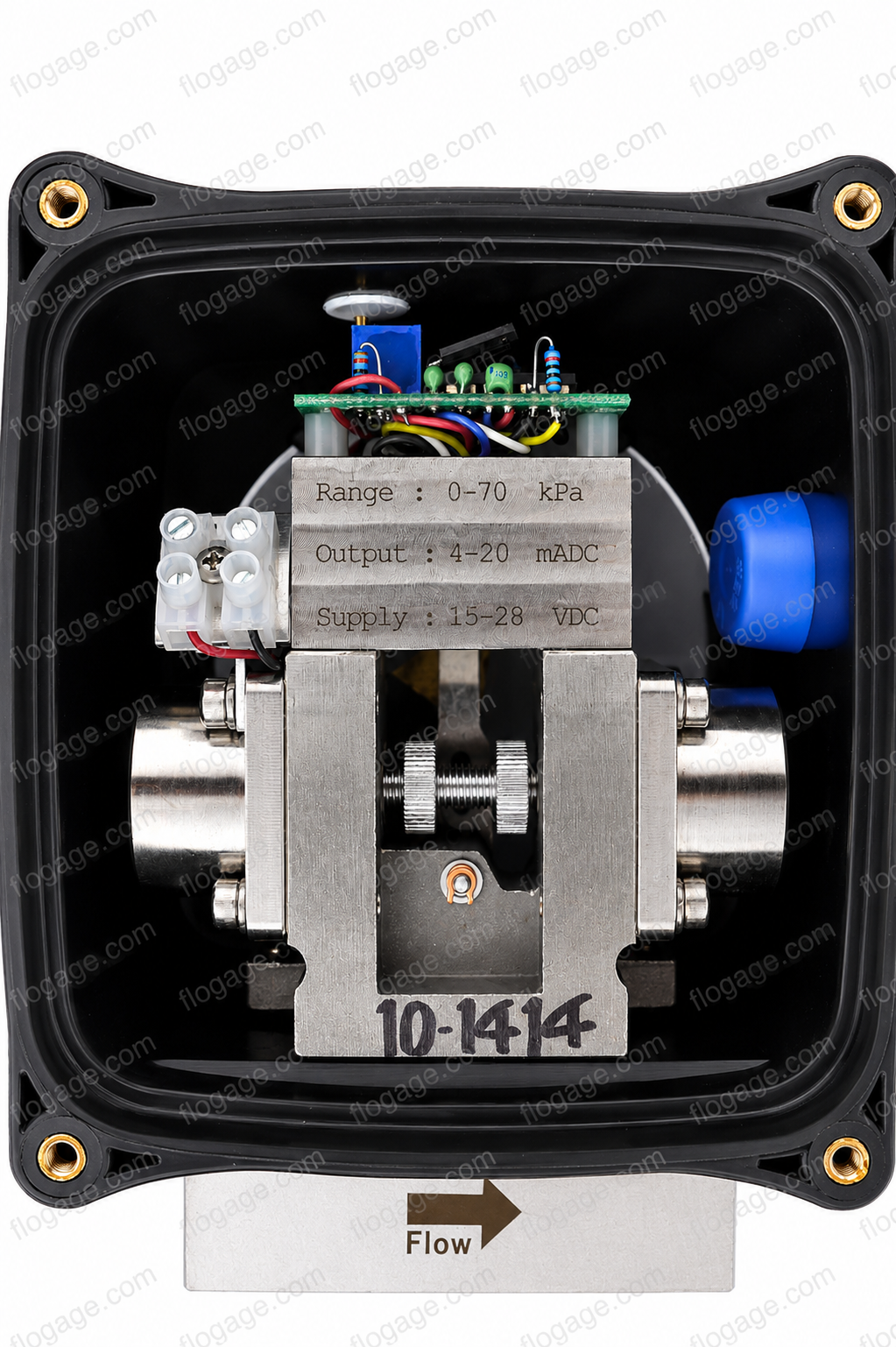
4-Wire Transmitter — Option W
4–20 mA DC, Linear Output
The W option provides a 4–20 mA DC output for interfacing with remote indicators, controllers, computers, and alarms. Uses a solid state Hall Effect sensor to detect the position of the pointer level mechanism. Low flow cutoff drives the output to 4 mA when flow drops below approximately 30% of full scale. Output is linear with flow rate.
| Output | 4–20 mA into 800 ohms max (linear with flow) |
| Accuracy (horizontal) | ±3% F.S. above 30% F.S. |
| Accuracy (vertical) | ±5% F.S. above 30% F.S. |
| Ambient Temp Limit | 120°F (50°C) |
| Power Input | 24 Vdc, 100 mA |
| Electrical Rating | General Purpose |
Note 8 — EMC: EMC compliance is available with Option W only when used with an aluminum housing (Option F or F2).
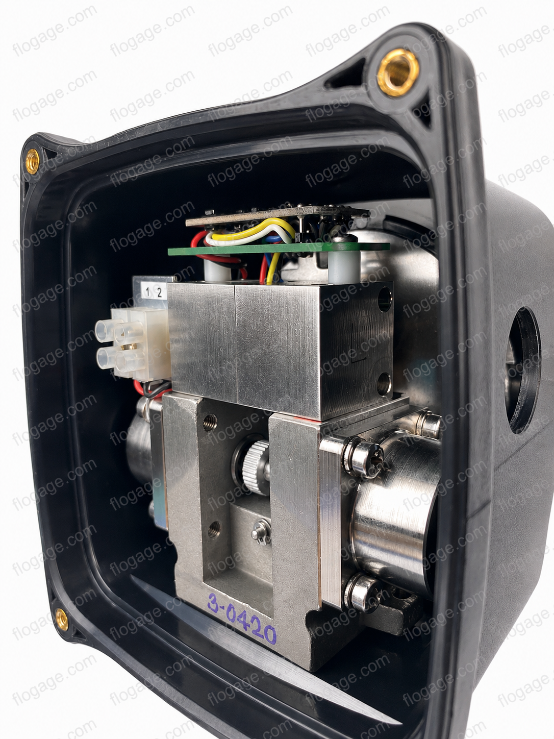
2-Wire Transmitter — Option W2
4–20 mA DC, with Mechanical Indicator
Option W2 uses a solid state strain-gauge to sense the differential pressure directly. Includes a mechanical flow indicator. Conditions which could cause the mechanical movement zero to shift will not affect the output from this transmitter. Provides improved rangeability at low flow rate and does not include a low flow cutoff. Output is proportional to flow rate squared (r²) — square root extraction is required in the receiving device.
| Output | 4–20 mA into 650 ohms max (proportional to flow²) |
| Accuracy (horizontal) | ±3% F.S. above 15% F.S. |
| Accuracy (vertical) | ±3% F.S. above 15% F.S. |
| Ambient Temp Limit | 120°F (50°C) |
| Power Input | 24 Vdc, 25 mA |
| Electrical Rating | CSA Approved — Ex ia IIC: Class I, Zone 0 |
Note 7 — Intrinsic Safety: CSA/NRTL Ex ia IIC T4 — Class I, Division I, Groups A, B, C, D; Class II, Groups E, F, G. KEMA 10 ATEX 0021 X: Ex ia IIC II IG T4, Zone 0 (per EN 60079-0:2009, EN 60079-11:2007, EN 60026-11:2007).
2-Wire Transmitter with HART — Option W2-1
4–20 mA DC + HART Protocol, with Mechanical Indicator
Option W2-1 is identical to W2 but adds HART (Highway Addressable Remote Transducer) digital communication superimposed on the 4–20 mA loop. Allows digital configuration, diagnostics, and process variable readout over the same two wires without interrupting the analog signal. Includes mechanical flow indicator. CSA approved for hazardous locations.
| Output | 4–20 mA into 650 ohms max (proportional to flow²) + HART |
| Accuracy (horizontal) | ±3% F.S. above 15% F.S. |
| Accuracy (vertical) | ±3% F.S. above 15% F.S. |
| Ambient Temp Limit | 120°F (50°C) |
| Power Input | 24 Vdc, 25 mA |
| Electrical Rating | CSA Approved — Ex ia IIC: Class I, Zone 0 |
Note 7 — Intrinsic Safety: CSA/NRTL Ex ia IIC T4 — Class I, Division I, Groups A, B, C, D; Class II, Groups E, F, G. KEMA 10 ATEX 0021 X: Ex ia IIC II IG T4, Zone 0 (per EN 60079-0:2009, EN 60079-11:2007, EN 60026-11:2007).
2-Wire Blind Transmitter — Option W3
4–20 mA DC, No Mechanical Indicator
Same as Option W2 but without the mechanical flow indicator. Ideal for remote monitoring applications where the local display is not required. CSA approved for hazardous locations.
| Output | 4–20 mA into 650 ohms max (proportional to flow²) |
| Accuracy | ±3% F.S. above 15% F.S. |
| Ambient Temp Limit | 120°F (50°C) |
| Power Input | 24 Vdc, 25 mA |
| Electrical Rating | CSA Approved — Ex ia IIC: Class I, Zone 0 |
Note 7 — Intrinsic Safety: CSA/NRTL Ex ia IIC T4 — Class I, Division I, Groups A, B, C, D; Class II, Groups E, F, G. KEMA 10 ATEX 0021 X: Ex ia IIC II IG T4, Zone 0 (per EN 60079-0:2009, EN 60079-11:2007, EN 60026-11:2007).
2-Wire Blind Transmitter with HART — Option W3-1
4–20 mA DC + HART Protocol, No Mechanical Indicator
Option W3-1 is identical to W3 but adds HART digital communication on the 4–20 mA loop. No local mechanical indicator — intended for fully remote monitoring installations where HART-enabled field communicators or DCS systems are used for configuration and diagnostics. CSA approved for hazardous locations.
| Output | 4–20 mA into 650 ohms max (proportional to flow²) + HART |
| Accuracy | ±3% F.S. above 15% F.S. |
| Ambient Temp Limit | 120°F (50°C) |
| Power Input | 24 Vdc, 25 mA |
| Electrical Rating | CSA Approved — Ex ia IIC: Class I, Zone 0 |
Note 7 — Intrinsic Safety: CSA/NRTL Ex ia IIC T4 — Class I, Division I, Groups A, B, C, D; Class II, Groups E, F, G. KEMA 10 ATEX 0021 X: Ex ia IIC II IG T4, Zone 0 (per EN 60079-0:2009, EN 60079-11:2007, EN 60026-11:2007).
Digital Display / Totalizer — Option RW3
2-Wire Loop Powered, Digital Rate & Total
The digital display flow meter is a 2-wire loop powered 4–20 mA DC indicator that displays flow rate and total. On-screen engineering units are easily configured. Password protection and 16-bit A/D resolution. Built-in wet/wet differential pressure sensor protected by an isolated stainless steel diaphragm. IP67 / NEMA 4X rated enclosure. Available in threaded or flanged connection and bronze or stainless steel construction.
| Display | 7 digits flow rate, 11 digits total |
| Output | 4–20 mA DC (non-linear) |
| Enclosure | IP67 / NEMA 4X |
| Resolution | 16-bit A/D |
| Connections | Threaded or Flanged |
| Body Materials | Bronze or 316SS |
Available Sub-Variants
Additional Output Options
Hi/Lo Alarm Relays
Two set-point relays. Contact rating: 3.0A @ 24V, 1.0A @ 117V, 0.5A @ 230V.
0–1000 Hz Frequency Output
1000 Hz F.S., 5V peak, 270 µs on time. For remote totalization.
Combined W + X + Y
Combines 4-wire transmitter, alarm relays, and frequency output in one unit.
Remote Digital Display
Remote display of rate and total in NEMA-4X enclosure. Requires W, W2, W3, or RW3. Power supply 24 Vdc, 100 mA.
Transmitter FAQ
Common questions about selecting, wiring, and using RCM flow meter transmitter options.
Choosing the Right Option
Wiring & Installation
Performance & Accuracy
EMC & Approvals
Still have questions about transmitter options?
Our engineering team is available Mon–Fri, 8:30am–4:30pm EST.
Flo-Gage™