Flow Meter Limit Switches
Options 1S2 and 2S2 — Reed Switch Limit Switches for Flow Sensing
Overview
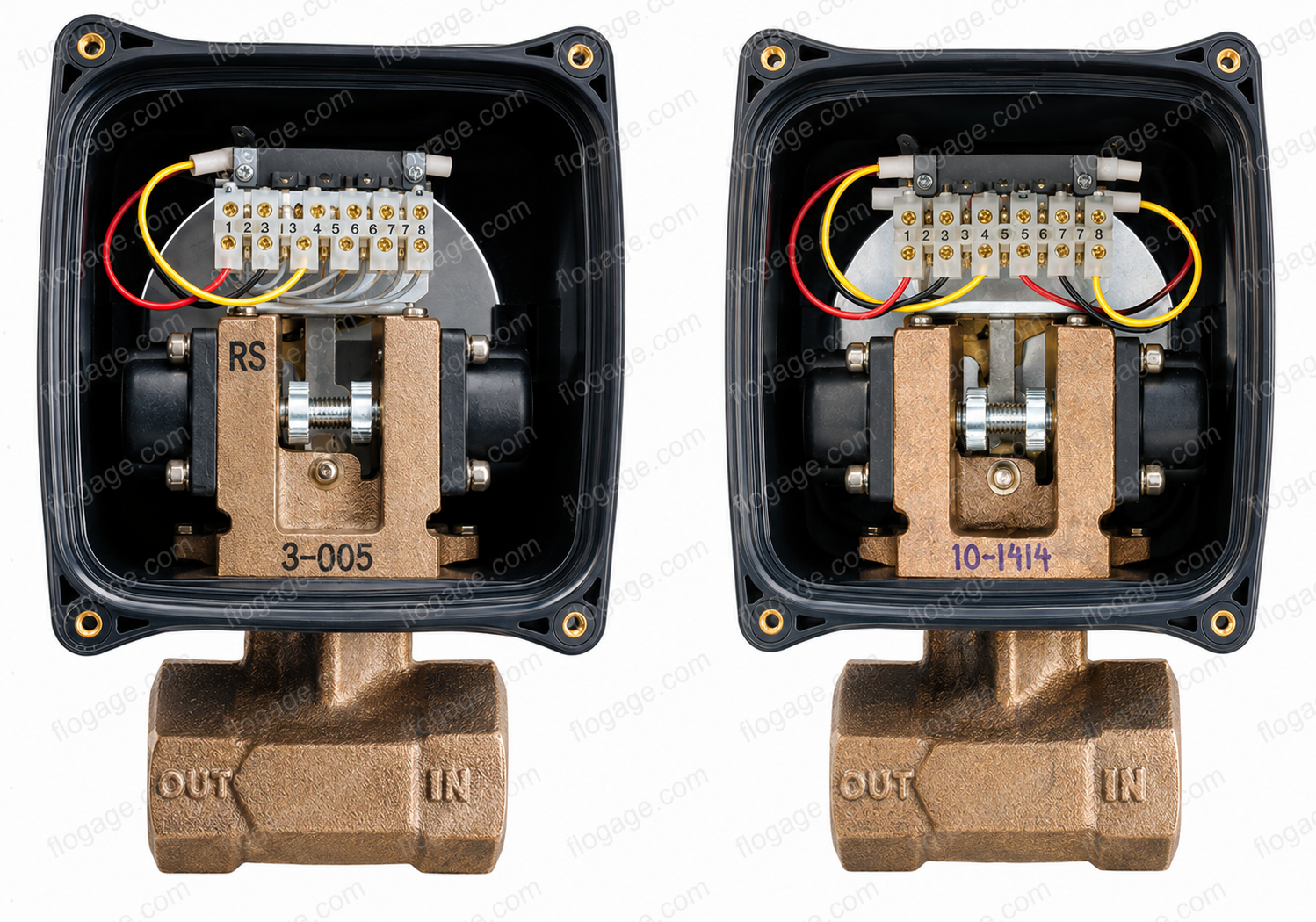 Option 1S2Option 2S2
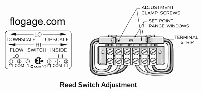
Flo-Gages can be ordered with either one (Option 1S2) or two (Option 2S2) reed switches suitable for sensing the actual flow rate. The RCM Flow Meter Limit Switches make or break contacts by detecting the position of a magnet which is permanently attached to the pointer mechanism on the flow indicator. This technique ensures constant correlation between the flow rate indicator and the flow switch.
In addition, it provides extremely reliable flow sensing which is highly immune to fouling by small particles in the flowing liquid. They can be ordered for use in a hazardous location environment (Option IS or Option IS-LED). LEDs provide viewing at a glance and easy field calibration. These switches are CSA and ATEX approved and operate in the most demanding environments.
Switch Options
Option 1S2 — Single Reed Switch
One single pole double throw (SPDT) reed switch. Independently adjustable from 30% to 90% of full scale. Use for low flow protection of equipment against loss of cooling or lubrication flow.
Option 2S2 — Dual Reed Switches
Two independent SPDT reed switches. Each independently adjustable from 30% to 90% of full scale. Use for both high and low flow alarm setpoints simultaneously.
Specifications
| Setability | ±5% F.S. |
| Repeatability | ±1% F.S. |
| Hysteresis | 7 to 13% F.S. |
| Contact Rating | 3 watts |
| Voltage (max) | 175 Vdc / 245 Vac |
| Current (switching) | 250 mA max |
| Current (carry) | 1.0 Amp max |
| Adjustment Range | 30% to 90% of full scale |
| Option 1S2 | 1 Reed Switch with SPDT |
| Option 2S2 | 2 Reed Switches with SPDT |
| Conduit Entrance | ½″ |
| Approvals | CSA and ATEX (intrinsically safe option) |
Applications
Low Flow Protection
Single switch set for low flow to protect equipment against loss of cooling or lubrication flow.
High Flow Warning
High flow switch provides warning of pipeline leaks or excess flow conditions.
Hazardous Locations
CSA/ATEX approved for Class I, Division 1 hazardous locations with Option IS.
Safety Interlocks
SPDT contacts allow easy configuration of safety interlock or control circuits.
Adjustment Procedure
Check the flow meter zero and correct if necessary using the coarse or fine zero procedure before proceeding.
Connect continuity tester to N.O. contact.
Loosen the switch clamp.
Establish the desired flow rate for switch tripping.
Slide the switch to the left-most position. Range window should show a partial or complete green mark.
Slowly slide to the right while monitoring N.O. contact. Switch will close.
Continue to slide to the right. Switch will open (false trigger).
Continue to slide to right until switch closes again.
Adjust by sliding to the right to raise set point, left to lower.
Tighten clamp. Note: Tiny adjustments may be required to reach the desired set point.
Limit Switch FAQ
Common questions about selecting, wiring, and using RCM flow meter limit switch options.
Choosing the Right Option
Specifications & Ratings
Installation & Wiring
Still have questions about limit switch options?
Our engineering team is available Mon–Fri, 8:30am–4:30pm EST.
Flo-Gage™