Options — Transmitters
Wiring & Calibration
Transmitter Options W2 & W3
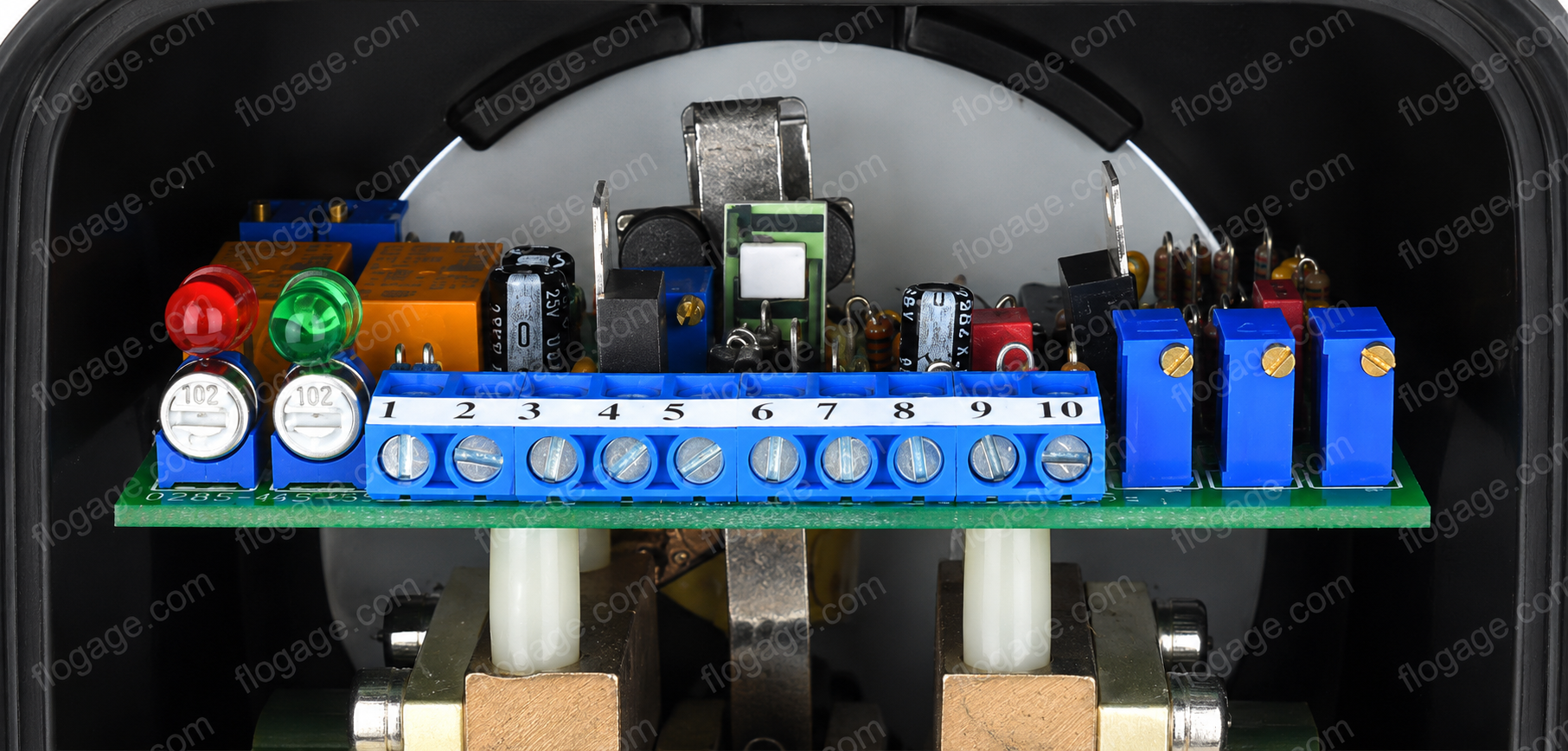
Installation, wiring, and field calibration instructions for the 4–20 mA DC transmitter options fitted inside the Flo-Gage™ enclosure.
1. Installation & Wiring
The transmitter board is fitted inside the enclosure of the Flo-Gage™. Both options use a solid-state strain gage to measure differential pressure directly — independent of the local mechanical indicator.
Option W2
- 4–20 mA DC output
- Local mechanical analog readout included
Option W3
- Operates identically to W2
- Local mechanical analog output omitted
Transmitter Operation
- Measures differential pressure directly using a solid-state strain gage
- Measured DP is independent of the mechanical measurement provided by the local indicator
- Transmitter output is linear with differential pressure
- Output must be linearized in the receiving device to provide a flow measurement
Power Requirements
Supply Voltage
24 VDC
External, user-supplied
Min. Current
25 mA
Minimum capacity required
Supplied By
User
Not included with meter
Startup Procedure
- 1Pressurize the pipeline.
- 2Check the zero.
- 3Adjust the zero potentiometer if necessary.
Figure 1 — Connection Diagram
Wiring Connections — Options W2 & W3
24 VDC Power Supply
Flo-Gage™ Transmitter Terminals
Optional Receiving Devices (connected in series)
Additional receivers may be connected in series. Observe power supply vs. maximum load impedance limits — see Figure 2.
Adjustment Potentiometers
Span Pot
20 mA adjustment
Zero Pot
4 mA adjustment
Figure 2 — Loop Impedance vs. Power Supply Voltage
| Option | Supply Voltage | Maximum Load Impedance |
|---|---|---|
| W2 and W3 | 24 VDC | 650 Ω |
| RW3 | 24 VDC | 350 Ω |
When connecting multiple receiving devices in series, ensure the total loop impedance does not exceed the maximum load for your supply voltage.
2. Field Calibration (4–20 mA DC)
2.1 Test Equipment
Recommended: Fluke 9600A digital multimeter or equivalent.
Connect in series with the current loop using the 24 VDC power supply.
2.2 Procedure
All meters are factory calibrated.
Do NOT adjust span unless you are certain the meter is reading incorrectly.
Warning
Do not attempt to adjust the span settings without:
- Proper test equipment
- Ability to establish a known steady flow rate close to full scale
Adjustment of the span WILL affect meter calibration.
Zero Calibration
- 1Connect multimeter in series with current loop.
- 2Pressurize the pipeline.
- 3Adjust zero potentiometer until current output reads 4.00 mA ±0.02 mA at no flow.
Span Calibration
- 1Establish a known flow rate through the meter — as close to 95% full scale as practical.
- 2Set span using the formula below.
Span Calibration Formula
I = 16Q² + 4.00
Example: at 95% FS → Q = 0.95 → I = 16(0.95)² + 4.00 = 18.44 mA
% Full Scale to Current Output
| % Full Scale | Current Output (mA) |
|---|---|
| 20% | 4.64 |
| 30% | 5.44 |
| 40% | 6.56 |
| 50% | 8.00 |
| 60% | 9.76 |
| 70% | 11.84 |
| 80% | 14.24 |
| 90% | 16.96 |
| 95% | 18.44 |
| 100% | 20.00 |
Note: Output is non-linear (quadratic) — linearize in receiving device.
W2 & W3 Transmitter FAQ
Common questions about wiring, signal linearization, and calibrating RCM Flo-Gage™ transmitter options W2 and W3.
Wiring & Power
Signal & Linearization
Calibration & Troubleshooting
Have a wiring or calibration question not covered here?
Our engineering team is available Mon–Fri, 8:30am–4:30pm EST.
Need a W2 or W3 Transmitter?
Transmitter options W2 and W3 can be factory-installed on any new Flo-Gage™ order, or retrofitted to existing meters. Contact our engineering team for compatibility and pricing.
Flo-Gage™