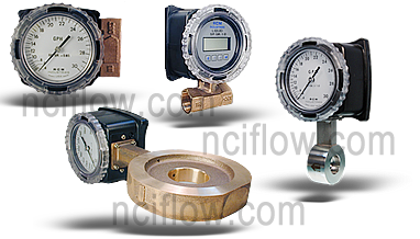
RCM liquid flow meters are suitable for potable and non-potable water, irrigation water, glycol-water mixtures, fuel oils, lubricating oils, gasoline and many other low and medium viscosity liquids (maximum viscosity 500 centipoise).
Meters are available in Bronze, Monel or 316SS.
Threaded Connections (Series 7000) from 1/4″ to 3″ in NPT or BSP.
Wafer Style (Series 8000) from 1/2″ to 8″.
Option: Flow Meter Configured Specifically for Liquid Ammonia Service
Liquid ammonia is used in industrial cooling systems, fertilizer and NOx emissions. Liquid ammonia service flow meters are constructed of stainless steel with EPR seals and a gasketed case. The flow meter has been developed for industrial applications where durability and reliability are important considerations in the monitoring of Liquid ammonia flow.
Standard Features:
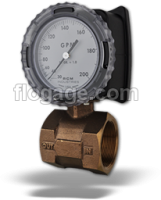
Sturdy in-line metal construction to withstand piping stresses without breaking.
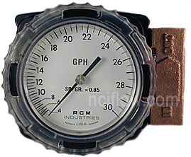
Black on white dial won’t crack, glaze or become hard to read with age.
Expanded 3.5″ (90mm) 270° analog dial for reading at a glance.
Suitable for use with both opaque and clear fluids.
Measures 6:1 range with 3% F.S. Accuracy.
Dial and case factory configured for quick installation – but easily field re-configured if needed.
Liquid flow ranges from 4 GPH (15 l/h) in 1/2″ meter to 3000 GPM (1200 l/m) in 8″ meter.
Selecting Meters for Liquid Service
The Flo-Gage can be used to meter flow rates of a wide variety of liquids including water, fuel oils (#2 through #6), lubricants, solvents and many chemical compounds.
For best accuracy, select a flow rate which will permit normal operation in the upper half of the meter scale.
The minimum flow rate which can be read is approximately 15% of the full scale flow rate for all meters. For best accuracy, select a flow rate which will permit normal operation in the upper half of the meter scale.
lnstallation Guidelines:
Provide 10 diameters of straight pipe in front of meter. Install control valves or solenoid valves downstream of meter if possible.
Mounting a wafer-style flow meter requires careful attention to alignment and proper compression to ensure accurate measurement and prevent leaks.
Here’s a general guide:
Preparation:
Inspect: Before installation, carefully inspect the flow meter and the mating flanges for any damage, debris, or foreign objects.
Clean: Ensure that both the inside of the pipeline and the sealing surfaces of the flanges and flow meter are clean and free of any particles.
Gaskets: Always use new gaskets that are compatible with the fluid, temperature, and pressure of the application. Place a gasket on each side of the wafer meter.
Alignment:
Straight Pipe Runs: Ensure there are adequate straight pipe runs upstream and downstream of the flow meter as specified by the manufacturer. This is crucial for accurate readings. The required length can vary depending on the meter type and upstream components but often ranges from 5 to 20 pipe diameters upstream and 2 to 5 diameters downstream.
Concentricity: The most critical step is to ensure that the mating pipes/flanges are perfectly concentric (aligned on the same center axis). Any misalignment can lead to uneven compression, leaks, and damage to the meter or gaskets.
Flange Spacing: The distance between the flanges should be precisely the thickness of the wafer flow meter plus the thickness of the two gaskets. Too much space will prevent proper compression, while too little will make insertion difficult and potentially damage the meter.
Installation:
Support: If necessary, provide temporary support for the meter during installation to prevent it from dropping or misaligning.
Insert: Carefully insert the wafer flow meter between the two flanges, ensuring the gaskets are correctly positioned on either side.
Bolt Pattern: Align the bolt holes of the meter with the holes in the flanges.
Tightening Sequence: Insert all bolts and hand-tighten them. Then, using a torque wrench, tighten the bolts in a crisscross or star pattern. Apply torque incrementally (e.g., 25%, 50%, 75%, 100% of final torque) to ensure even compression across the gaskets and prevent stress on the meter body.
Avoid Over-tightening: Over-tightening can damage the gaskets, deform the meter body, or lead to premature failure. Consult the manufacturer’s recommended torque specifications.
Flow Direction:
Check Arrow: Most flow meters have an arrow on their body indicating the direction of fluid flow. Ensure the meter is installed with this arrow pointing in the correct direction of your process flow.
Post-Installation:
Leak Check: After installation and before full operation, perform a pressure test and leak check to ensure all connections are sealed properly.
Important Considerations:
Vibration: Minimize vibration to the meter by ensuring proper pipe supports are in place.
Services Not Recommended:
Flo-Gages are not recommended for the following kinds of service:
Resins, paints or monomers which can form solid deposits in the piping system.
“Super-solvents” which attack most available elastomers.