RCM Flow Switches
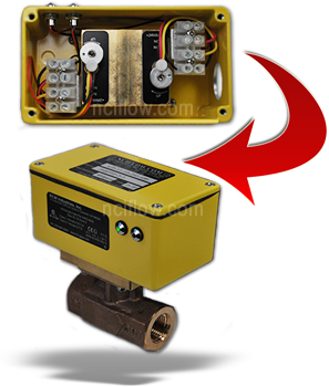
A flow switch with reed switches, specifically designed for use in a hazardous location environment (Option 1S2-IS, 1S2-IS-LED or Option 2S2-IS, 2S2-IS-LED). LED’s provide viewing at a glance and easy field calibration. These switches are CSA and ATEX approved and operate in the most demanding environments. RCM flow switches provide an economical solutions for equipment protection and automation. Our general purpose reed switches make or break contacts by detecting the position of a magnet permanently attached to the bellow.
Standard Specifications: (NEMA-4X / IP66)
Accuracy: ± 3% F.S.
Repeatability: ± 1% F.S.
Pressure Max.: 400 psig (28.1 kg/cm2)
Pressure Min.: 10 psig (0.67 kg/cm2)
Temp. Max.: 212ºF (100ºC)
Temp. Min.: -30ºF (-34ºC)
Enclosure Rating: NEMA 4X / IP66
Electrical Rating:
Ambient Temp.: 120ºF (50ºC)
Setability: ± 5% F.S.
Hysteresis: ± 13% F.S.
Contact Rating: 10 Watts, 175 Vdc max. 125 Vac max.
Current: 350 mA max. switching
Hazardous Location Specifications: (Option IS & LED)
Contact Rating:
Vmax = 28V, Imax = 110mA, Pmax = 1.2W, Ci = 0uF, Li = 0uH
CSA / NRTLc: AEx ia IIC: Class I, Division I, Groups A, B, C & D Class II, Division I, Groups E, F & G
KEMA: Ex ia IIC: Zone 0, II 1G T4 0°C ≤ Ta ≤ 50°C ATEX EC Type Examination
Protect from freezing liquid
Hazardous Location Specifications: (Option IS & LED)
Contact Rating:
Vmax = 28V, Imax = 110mA, Pmax = 1.2W, Ci = 0uF, Li = 0uH
CSA / NRTLc: AEx ia IIC: Class I, Division I, Groups A, B, C & D
Class II, Division I, Groups E, F & G
KEMA: Ex ia IIC: Zone 0, II 1G T4 0°C ≤ Ta ≤ 50°C ATEX EC Type Examination
Selecting a Flow Switch
Select a switch with a maximum flow range greater than the required switch point. Best performance at minimum pressure drop occurs at approximately 50% of maximum flow range.
Select a) body size, b) end connections, c) material, d) maximum flow rate, e) options (if required) and f) number of switches.
A) BODY SIZE
pipe size at the meter inlet. Select from Standard Flow Ranges and Sizes
B) SERIES (end connections)
1 – threaded units provided with FNPT connections standard. FBSP parallel threads available on request for bronze meters.
2 – wafer units mount between any standard 150 or 300 class flanges (or international equivalent).
C) MATERIAL
1 = Bronze 3 = Stainless steel (316)
D) FLOW RATE
(maximum) – Select from Standard Flow Ranges and Sizes, page 2. Prefix full scale with “M” for metric units.
E) OPTIONS
Select from table of Options. Note: For gas service, select option I and specify gas being ———measured, inlet temperature and pressure
F) NUMBER OF SWITCHES
1S2 – One single pole double throw switch 2S2 – Two single pole double throw switches
G) IS – Intrinsic Safe Approval (Included w / 1S2 or 2S2 Only).
H) LED – Light Emitting Diode (optional no charge).
| Specifications | Standard | Optional |
|---|---|---|
| Maximum Pressure | 400 psig, (28.1 kg/cm2) | |
| Maximum Temperature | 212F (100C) | 350F (177C) |
| Minimum Temperature | -30F (-34C)nProtect from freezing liquids | -80F (-62C) |
| Pressure Drop | 5 psig at max flown1.2 psig at 50% of max flow | |
| Housing | Polycarbonate | Aluminum |
| Pressure Cell | Aluminum, hard anodized | |
| Body | Bronze | 316SS or Monel |
| Bellows | Bronze | 316SS, Monel or Inconel |
| Gear Movement | Bronze | 316SS |
| Reed Switches | |
|---|---|
| Setability | u00b15% FS. |
| Repeatability | u00b11% FS. |
| Hysteresis | 7 to 13% FS. |
| Contact Rating | 3 watts |
| Voltage | 100 vdc u2013 max. |
| Current | 250mA max. switching 250mA max. switching 1.0 Amp max. carry |