Digital Flow Meter
- Digital Display Rate & Total – Option RW3
- Remote Digital Display Rate & Total – Option RD-1
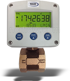
The RCM Digital flow meter display is a 2 wire loop powered 4-20mA DC transmitter features 7 digits for flow rate and 11 digits for accumulated total. On-screen engineering units are easily configured, while different units for flow rate and total can be displayed simultaneously. A wide selection of options further enhances this models capability. Optional back-lighting is available for easy viewing.
Wet/wet differential pressure sensor is protected by an isolated stainless steel diaphragm for measuring liquids, gases and conductive flow media.
The digital display can be connected as a remote display (option DR-1) to our 4-wire transmitter output option W (4-20mA linear output signal), 2-wire loop powered transmitter option W2 or W3 (4-20mA loop powered signal) output is proportional to flow rate squared or our 2-wire loop powered transmitter option RW3 which is self-contained and complete.
RCM Industries has been manufacturing quality flow measuring products for over 35 years for end-users and OEM applications.
Standard Features:
- 15 Point Linearization of Flow Curve
- Displays Instantaneous Flow Rate, Total & Accumulated Total
- Large 17mm (0.67) Digit for Flow Rate or Total
- Operational Temperature -30 to 80C (-22 to 178F)
- Rugged Enclosure IP67/NEMA 4X Rated **
- Wet / Wet Differential Pressure Sensor
- Amber or Green Backlighting (Optional)

** IP67 indicates that this enclosure is dust-tight and water-tight up to 1 meter immersion depth.
** NEMA 4X Enclosure Characteristics:
- Indoor or outdoor use, including offshore applications
- Protection against windblown dust and rain
- Protection from splashing water and hose-directed water
- Corrosion-resistant
Standard Specifications:
- Accuracy: ± 3% F.S.
- Repeatability: ± 1% F.S.
- Pressure Max.: 180 psig (12.6 kg/cm2)
- Pressure Min.: 10 psig (0.67 kg/cm2)
- Temp. Max.: 212ºF (100ºC)
- Temp. Min.: -30ºF (-34ºC)
- IP67 / NEMA 4X Rated Enclosure
Electrical Rating:
Power Input:
100mA, 24Vdc power supply 20-30Vdc (Not Included)
Input loop powered from 4-20mA signal. Voltage drop max. 2.6V
Display:
Rate Display:
High intensity reflective numeric and alpha numeric LCD, UV resistant
User definable, 8 times/sec – 30 secs.
Password Protection
7 and 11 digit various symbols and measuring units
Environmental:
Operating Temperature: -30ºF (-34ºC) to 212ºF (100ºC)
Humidity: 0-90% Noncondensing
Accuracy:
0.5% F.S. (Non-linearity, Repeatability and Hysteresis
Stability:
0.5%F.S./year
Signal Inputs:
Full Scale Range: 4 to 20 mA DC
Loop Voltage Drop: 2.6 Volts Max. at 20mA
Update Time: 4 times/sec.
Span: 0.001/999,999 with available decimal position
16 Bit resolution, error < 0.01mA/+- 0.05% F.S.
Low cutoff supplied to inhibit indications at low flow rates
Signal Ouput:
The pulse output transmitting accumulated total
Type: one passive transistor output (NPN)
Max. 500Hz pulse length user definable between 1 msec up to 10 sec.
Calibration & Operation:
Input Scaling: Via front keypad
Decimal Point: Via front keypad
Reset Input: Via front keypad
Keypad: 3 tactile feedback keys
Wiring Overview
This document explains the installation, wiring, calibration, and programming of the Digital Display Option R (built-in) and the DR-1 remote display accessory for Flo-Gage systems.
The display processes a 4–20 mA DC signal to show flow rate and totalization, with options for linear or square root scaling and pulse output for remote totalizers.
1. Installation & Wiring
General:
- Designed for direct mounting in the Flo-Gage housing or as a remote display.
- Displays up to 4½ digits for rate and 8 digits for totalization.
- Provides isolated open-collector pulse output for remote totalizing or external devices.
- Requires a 4–20 mA loop-powered signal from transmitter options W2 or W3.
Built-in and Remote Wiring:
- Includes wiring diagrams for both internal and external (DR-1) configurations.
- Caution: Pulse output polarity must be correct; voltages over 30 V can damage the circuit.
- Figures illustrate pulse output conversion and waveform.
2. Programming Definitions
The programming menu allows customization of display and scaling functions.
Key programmable parameters include:
- ent code: Password entry (if lock is on).
- clr tot: Clear totalizer.
- 3 or 4: Choose 3.5 or 4.5 rate digits.
- dec loc / tdec: Set decimal point locations for rate and totalizer displays.
- tot desc / rat desc: Select engineering units (GAL, LIT, FT³, M³) and rate time base (/sec, /min, /hr).
- input: Choose linear or square root extraction.
- rate lo / rate hi: Define the 4 mA and 20 mA corresponding rates.
- lo cut: Set low cutoff percentage.
- pulseout: Set pulse output divider (÷1, ÷10, ÷100, or off).
- cal / cal LO / cal HI: Calibration steps for input scaling.
- loc code / loc unit: Configure access lock and password.
3. Programming Flow
A step-by-step flowchart details how to:
- Enter and navigate programming mode.
- Set display resolution, units, scaling, and calibration.
- Adjust pulse output, low cutoff, and locking options.
- Save settings before returning to run mode (do not remove loop power mid-program).
4. Error Codes
| Error | Description |
|---|---|
RATE ERR |
Rate low ≥ rate high; re-enter values. |
cal ERR |
Calibration input out of range. |
e pulse |
Totalizing too fast for pulse output; increase divider or turn off. |
e battry |
Low battery or invalid memory detected; replace battery and reinitialize. |
5. Battery Replacement
- Battery: Panasonic BR2330 (3V Lithium).
- Maintain loop power during replacement to preserve calibration.
- Reinitialize and recalibrate if loop power is lost.
- Battery polarity must be correct (+ on top).
6. Dimensions
- DR-1 Remote Display: 4.92″ x 4.21″ front face
- Panel-mounted with four screws,
- Terminals accessible beneath cover.
7. Specifications
Power & Display
- Loop powered (4–20 mA); internal 3V lithium battery for memory.
- Rate: 3.5/4.5 digits, updates every 2 seconds.
- Totalizer: 8 digits up to 99,999,999.
- Decimal and unit selection flexible.
- Low-battery indicator (“BAT” flashes).
Environmental
- Operating range: -4°F to +158°F (standard) or -22°F extended.
- Humidity: 0–90% non-condensing.
Accuracy
- ±0.1% full scale, ±1 count.
- Temp drift: 50–200 ppm/°C.
Inputs
- 4–20 mA signal, reverse-polarity protected, 6V drop max.
- Reset via front keypad or contact closure.
- 16-bit resolution, 1 sample every 2 seconds.
Pulse Output
- Opto-isolated open collector.
- 30V max, 25 pulses/sec max.
- Divider: ÷1, ÷10, ÷100, or off.
Lockout Options
- Software password (4 digits).
- Hardware jumper for sealed lockout.
In summary
The Digital Display Option R / DR-1 is a robust, programmable, loop-powered flow display capable of displaying rate and total flow, offering scalable pulse output, lockout protection, and simple front-panel calibration. It’s ideal for applications requiring accurate digital indication and remote totalization of 4–20 mA signals