RCM Gas Flow Meters
RCM Series 7000 and RCM Series 8000

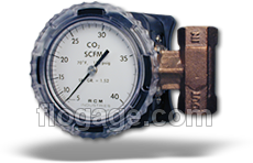
The RCM gas flow meters are well suited to monitoring compressed air flow rates. These meters plumb directly into the pipelines and require no external power connections. Use these meters to determine the air consumption of tools for improved accounting and increased efficiency. The Flo-Gage flow meter has been developed for industrial applications where durability and reliability are important considerations in the monitoring of flow. The Flo-Gage has accuracy for most industrial processes and is particularly suited for applications where compactness, low cost, minimal maintenance and resistance to accidental damage are important factors. Other compressed gases can be monitored as well. Common gases monitored include nitrogen, oxygen, argon, carbon dioxide, natural and LP gases.
- Meters are available in Bronze, Monel or 316SS.
- Threaded Connections (Series 7000) from 1/4″ to 3″ in NPT or BSP.
- Wafer Style (Series 8000) from 1/2″ to 8″.

Standard Features:
- Sturdy in-line metal construction to withstand piping stresses without breaking.
- Black on white dial won’t crack, glaze or become hard to read with age.
- Expanded 3.5″ (90mm) 270° analog dial for reading at a glance.
- Suitable for use with both opaque and clear fluids.
- Measures 6:1 range with 3% F.S. Accuracy.
- Dial and case factory configured for quick installation – but easily field re-configured if needed.
- Gas flow ranges from 40 SCFH (1 Nm3/h) in 1/2″ meter to 20,000 SCFM (600 Nm3/m) in 8″ meter.
 Option: Flow Meters Configured Specifically for Ammonia Gas Service
Ammonia gas is used in distillation plants and as a cooling agent. Our Ammonia gas flow meters offer all stainless steel construction to withstand the harsh environment. EPR seals and a gasketed case are standard features for additional protection. The Ammonia gas flow meter has been developed for industrial applications where durability and reliability are important considerations in the monitoring of ammonia gas flow.
Selecting Meters for Gas Service
- The Flo-Gage can be used to measure flow rates of various gases such as air, nitrogen, oxygen, carbon dioxide, hydrogen, propane, methane (natural gas), argon, helium, sulfur dioxide, etc.
- For best accuracy, select a flow rate which will permit normal operation in the upper half of the meter scale.
- To choose the proper meter, select pipe size and full scale flow rate from the chart of “Standard Flow Rates and Body Sizes“.
- To insure satisfactory operation, pressure should be not less than 10 psig at the meter inlet.
Minimum Flow Rates
The minimum flow rate which can be read is approximately 15% of the full scale flow rate for all meters. For best accuracy, select a flow rate which will permit normal operation in the upper half of the meter scale.
lnstallation Guidelines
Provide 10 diameters of straight pipe in front of meter. Install control valves or solenoid valves downstream of meter if possible.
Mounting a wafer-style flow meter requires careful attention to alignment and proper compression to ensure accurate measurement and prevent leaks.
Here’s a general guide:
- Preparation:
- Inspect: Before installation, carefully inspect the flow meter and the mating flanges for any damage, debris, or foreign objects.
- Clean: Ensure that both the inside of the pipeline and the sealing surfaces of the flanges and flow meter are clean and free of any particles.
- Gaskets: Always use new gaskets that are compatible with the fluid, temperature, and pressure of the application. Place a gasket on each side of the wafer meter.
- Alignment:
- Straight Pipe Runs: Ensure there are adequate straight pipe runs upstream and downstream of the flow meter as specified by the manufacturer. This is crucial for accurate readings. The required length can vary depending on the meter type and upstream components but often ranges from 5 to 20 pipe diameters upstream and 2 to 5 diameters downstream.
- Concentricity: The most critical step is to ensure that the mating pipes/flanges are perfectly concentric (aligned on the same center axis). Any misalignment can lead to uneven compression, leaks, and damage to the meter or gaskets.
- Flange Spacing: The distance between the flanges should be precisely the thickness of the wafer flow meter plus the thickness of the two gaskets. Too much space will prevent proper compression, while too little will make insertion difficult and potentially damage the meter.
- Installation:
- Support: If necessary, provide temporary support for the meter during installation to prevent it from dropping or misaligning.
- Insert: Carefully insert the wafer flow meter between the two flanges, ensuring the gaskets are correctly positioned on either side.
- Bolt Pattern: Align the bolt holes of the meter with the holes in the flanges.
- Tightening Sequence: Insert all bolts and hand-tighten them. Then, using a torque wrench, tighten the bolts in a crisscross or star pattern. Apply torque incrementally (e.g., 25%, 50%, 75%, 100% of final torque) to ensure even compression across the gaskets and prevent stress on the meter body.
- Avoid Over-tightening: Over-tightening can damage the gaskets, deform the meter body, or lead to premature failure. Consult the manufacturer’s recommended torque specifications.
- Flow Direction:
- Check Arrow: Most flow meters have an arrow on their body indicating the direction of fluid flow. Ensure the meter is installed with this arrow pointing in the correct direction of your process flow.
- Post-Installation:
- Leak Check: After installation and before full operation, perform a pressure test and leak check to ensure all connections are sealed properly.
Important Considerations:
- Vibration: Minimize vibration to the meter by ensuring proper pipe supports are in place.
Services Not Recommended
Flo-Gages are not recommended for the following kinds of service:
- Resins, paints or monomers which can form solid deposits in the piping system.
- “Super-solvents” which attack most available elastomers.
- Sulfuric acid in any concentration.
- Foams which tend to have inconsistent densities.
- Toxic substances requiring hermetically sealed enclosures.
- Fluids with viscosity above 500 centipoise.
- Pumping systems using piston pumps which produce non-steady flow conditions.
- Gravity-fed systems having less head than the pressure loss across the meter at normal operating conditions.
| Specifications | Standard | Optional |
|---|---|---|
| Series 7000 | FNPT (threaded) Standard | |
| Series 8000 | Wafer unit mount between 150 or 300 class flanges. | |
| Housing | UV Stabilized Polycarbonate | Aluminum |
| Body | Bronze | Monel / 316SS |
| Bellows | Bronze | Monel / 316SS / Inconel |
| Seals | Buna N | Viton / EPR / Teflon |
| Crystal | Polycarbonate | Glass |
| Gear Movement | Bronze | 316SS |
| Accuracy | u00b1 3% F.S. | u00b1 3% F.S. |
| Repeatability | u00b1 1% F.S. | u00b1 1% F.S. |
| Maximum Pressure | 180 psig (12.6 kg/cm2) | 400 psig (28.1 kg/cm2) |
| Minimum Pressure | 10 psig (0.67kg/cm2) | 10 psig (0.67kg/cm2) |
| Maximum Temperature | 212 F (100 C) | 350 F (177 C) |
| Minimum Temperature | -30 F (-34 C) | -80 F (-62 C) |