Flow Meter Limit Switches
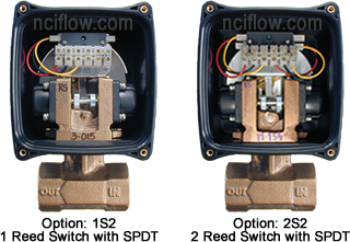
OPTIONS 1S2 AND 2S2: REED SWITCHES. Flo-Gages can be ordered with either one (Option 1S2) or two (Option 2S2) reed switches suitable for sensing the actual flow rate. The RCM Flow Meter Limit Switches make or break contacts by detecting the position of a magnet which is permanently attached to the pointer mechanism on the flow indicator. This technique constant correlation between the flow rate indicator and the flow switch. In addition it provides extremely reliable flow sensing which is highly immune to fouling by small particles in the flowing liquid.
They can be ordered for use in a hazardous location environment (Option IS or Option IS-LED). LED’s provide viewing at a glance and easy field calibration. These switches are CSA and ATEX approved and operate in the most demanding environments.
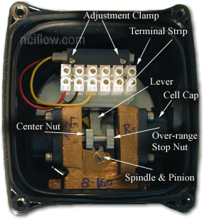
Each switch is independently adjustable from 30% to 90% of full scale. Switches are factory set to specified flow rates (30% to 90% FS if not specified). Switches are single-pole double-throw for ease in configuring a safety interlock or control circuit.
Tamper resistant switches are located inside the meter and accessed by removing the hack cover. Switches are hermetically sealed in glass and then epoxy potted.
A 1/2″ conduit entrance and a built-in terminal strip are provided for ease of connection.
APPLICATIONS: Use a single reed switch set for low flow to protect equipment against loss of cooling or lubrication flow. A high flow switch provides warning of pipeline leaks.
ORDERING INFORMATION: Reed switches are available with all options except, K, N, W, W2, W3, X, Y and Z
Specifications – RCM Flowmeter Limit Switches
Setability: ±5% F.S.
Repeatability: ±1% F.S.
Hysteresis: 7 to 13% F.S.
Contact Rating: 3 watts
Voltage: 175 Vdc (max) / 245 Vac (max)
Current: 250 mA max switching / 1.0 Amp max. carry
Option: 1S2 1 Reed Switch with SPDT
Option: 2S2 2 Reed Switches with SPDT